Editor
Editor is the structured authoring surface for model metadata, initialization, states, events, actions, and transitions. It edits the same semantic model shown by Chart, so a change committed in either surface appears in the other.
The States, Events, and Actions catalogs each show Name and Description. Name occupies one third of their combined width and Description two thirds, for both headers and rows. Long content wraps, and the proportions remain the same at narrow widths.
State Machine Information
Select Editor in the Model tree to open State Machine Info. This read-only dashboard contains five groups:
- Model Metadata shows the project name, description, and model version.
- Initialization shows the selected initial state.
- Validation shows the latest result and counts for states, events, declared actions, entry actions, exit actions, and transitions.
- Hosted Model shows the server connection, readiness, hosted revision, and whether the client and hosted models are synchronized.
- Simulation currently displays None. Inspect live session state on Simulator and in the status bar and Console.
Use Validate State Machine at the bottom of the page to run a complete validation and publish its diagnostics to the Console.
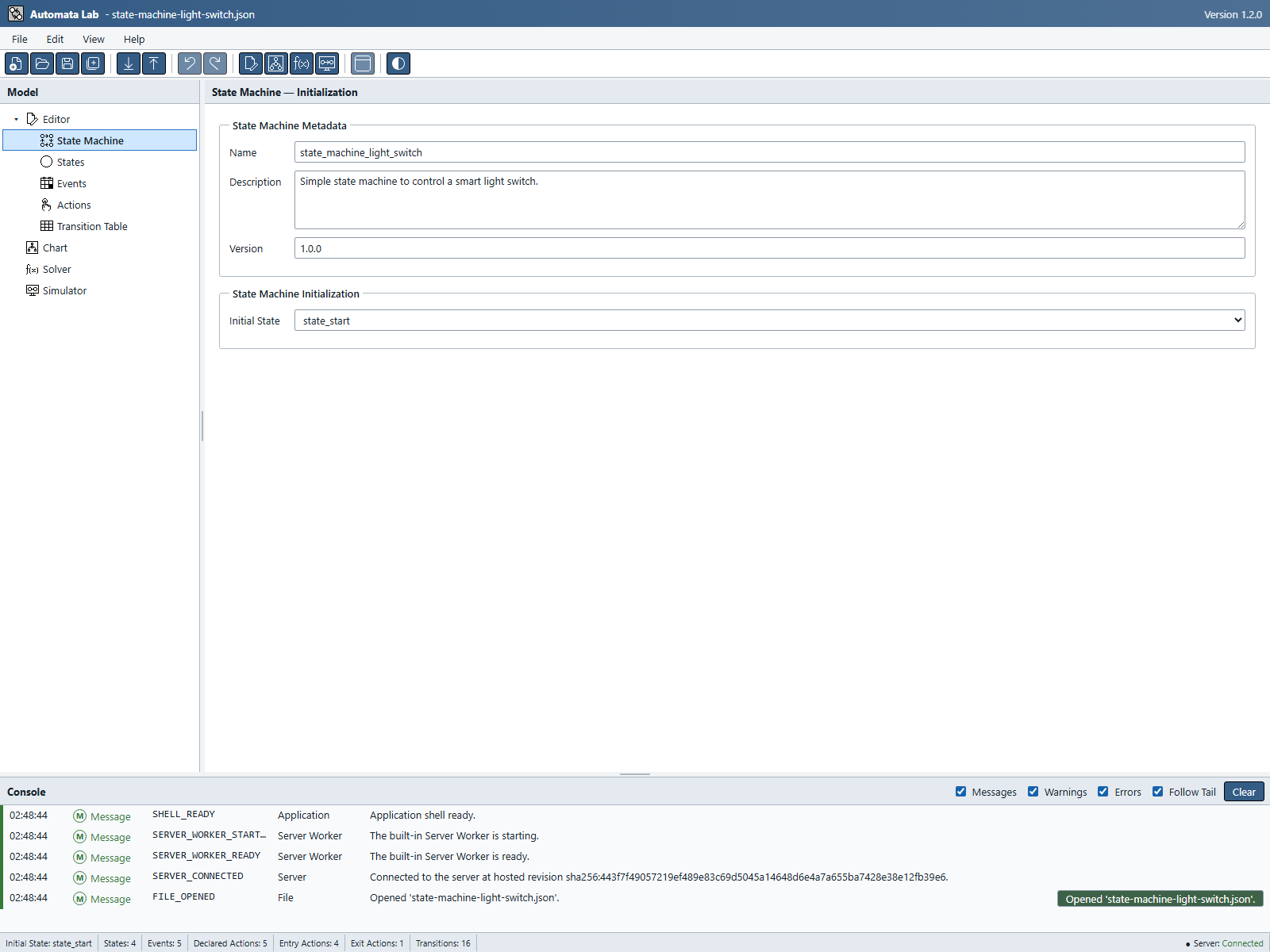
To edit metadata or initialization, expand Editor and select State Machine. Enter the Name, Description, and semantic model Version, then select an Initial State from the declared state catalog. A new draft may leave the initial selection blank. Validated metadata edits commit when focus leaves the field or you navigate away.
The model Version must use Semantic Versioning, such as 1.0.0. It describes your state-machine model and is independent of the Automata Lab application and JSON file-format versions.
Figure UG-02 shows the editable State Machine page for the example.
States
Select Editor → States to manage the ordered state catalog. The States list provides Move Up, Move Down, Add, Delete, and Edit.
To create a state:
- Select Add.
- Enter a unique, non-empty Name and an optional Description.
- Confirm the dialog.
Select a state and choose Edit to change it. A rename updates the initial-state selection, transitions, action assignments, Chart placement, and other typed references in one atomic operation. Moving a state changes display order only.
Terminal State appears in state Add/Edit dialogs and defaults unchecked for a new state. Confirm updates the flag and its Chart notation in one undoable command. Clearing it removes the relation while retaining the indicator; shared indicators and other states remain intact. Cancel, Close and Escape discard the draft. Events and Actions have no terminal checkbox.
The right side of the page contains the selected state's Entry Actions and Exit Actions tabs. If no state is selected, association commands that require one remain disabled. The active tab is slightly lighter than the inactive tab in either theme. The page initially allocates 60 percent of its width to the state catalog and 40 percent to the action tabs; drag the splitter to adjust this independently of the catalog columns.
Entry Actions
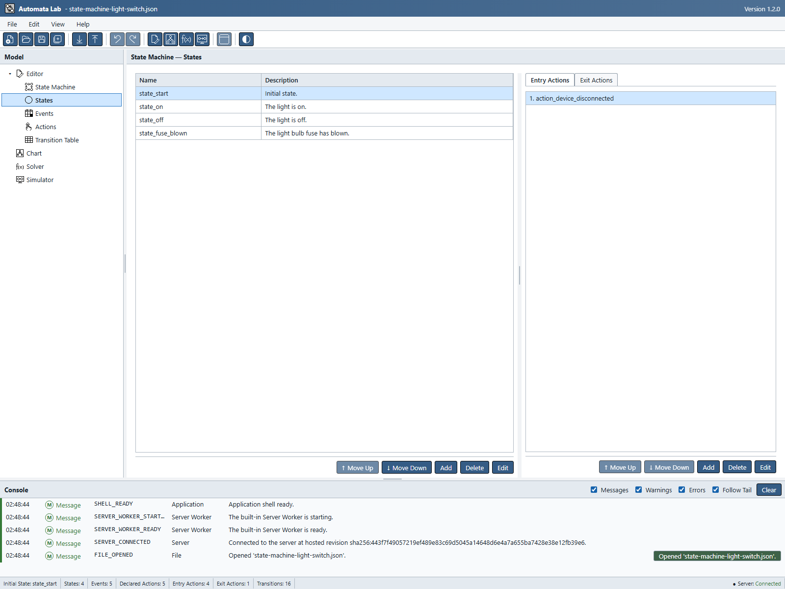
Select a state, then open the Entry Actions tab to define the ordered actions reported after the runtime enters that state.
- Choose Add.
- Select an action from the declared action catalog.
- Confirm the assignment.
- Use Move Up and Move Down to set output order.
Repeated assignments are allowed and remain visible. Edit replaces the selected assignment with another declared action, and Delete removes that occurrence only. If the action catalog is empty, add actions on the Actions page before assigning them.
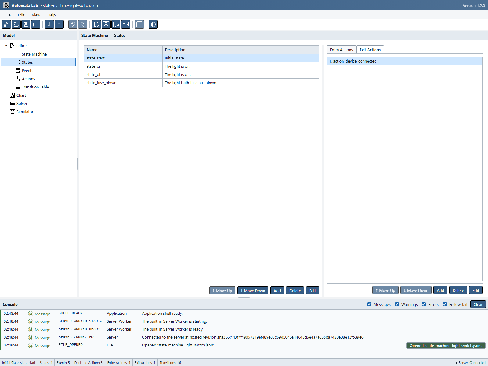
Compare Figure UG-03 with Figure UG-04 to see the two independent schedules for the same state.
Exit Actions
Select a state, then open the Exit Actions tab to define the ordered actions reported before the runtime leaves that state. Add, edit, move, and delete assignments in the same way as Entry Actions.
Entry and exit schedules are independent. The same action may occur in both lists or appear repeatedly within either list. The list order is semantic: changing it changes the order reported by the runtime.
Figure UG-04 keeps the same state selected and shows its Exit Actions tab.
Events
Select Editor → Events to manage the ordered event catalog. Use Add or Edit to supply a unique, non-empty Name and optional Description. Duplicate names are rejected.
Renaming an event updates every transition and detached Chart draft that remembers it. Deleting an event first shows the transitions that will be removed and draft event memories that will be cleared. Event catalog order affects display only.
Actions
Select Editor → Actions to manage the reusable action catalog. Each action has a unique, non-empty Name and optional Description.
The catalog does not contain separate entry and exit action types. A state's association list determines when an action is reported. Renaming an action updates every entry and exit assignment. Deleting one first shows all affected assignments. Action catalog order affects display only.
Transition Table
Select Editor → Transition Table to edit transitions in a three-column grid:
| Column | Selection |
|---|---|
| State | Source state |
| Event | Declared input event |
| Next State | Destination state |
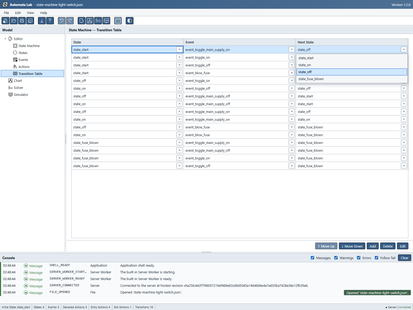
Use Add to create a row through the Transition dialog, or select a grid cell and open its drop-down button to choose from current declarations. Grid cells do not accept free text. An accepted cell selection commits the complete row edit immediately. The dropdown arrow controls retain theme colors independently of the Application Buttons setting. They use the same compact 24-by-22.4-pixel size and equal 3.3-pixel top, right, and bottom insets as panel close controls.
Figure UG-05 shows where to open a cell's list of valid destinations.
The source State and Event form a unique key. If another row already uses the same pair, the edit is rejected without a partial change. Self-transitions are valid: choose the same state in the State and Next State columns.
Use Edit for the dialog-based alternative, Delete to remove the selected transition after impact confirmation, and Move commands to change display order. Row order does not affect runtime selection.
Renaming and Deleting Model Elements
Renames and deletions operate on references, not unrelated matching text. A successful rename updates every affected semantic and Chart reference as one document command.
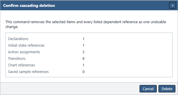
Deleting from the States, Events, Actions, or Transition Table page opens an impact confirmation that lists the selected item and its dependent data. Review that list before confirming:
- Deleting a state can remove transitions, action assignments, and Chart placement; deleting the initial state also clears the initial-state selection. Attached Chart drafts survive with the affected ends released at their last effective coordinates;
- Deleting an event can remove transitions that use it and clear that event from remembered Chart drafts. Those drafts and their state attachments survive;
- Deleting an action can remove its entry and exit assignments; and
- Deleting a transition removes that semantic row and its derived Chart relation.
The dialog's explicit Delete action initially receives focus, so pressing Enter confirms the displayed plan. Cancel commits nothing. Chart uses the same atomic deletion rules but applies a Chart selection immediately when you press Delete outside an editable control.
Figure UG-06 shows the impact to review before deleting the example's initial state.
Undo and Redo
Every successful Editor mutation is one atomic document command. It marks the project dirty, advances the document revision once, and records the inverse operation for Undo. A rejected or cancelled command makes no change.
Use Edit → Undo, Edit → Redo, or their toolbar and keyboard equivalents. One Undo restores the complete effect of a rename, confirmed cascade deletion, reorder, or accepted transition-cell edit.
Undo and Redo history belongs to the current authoring project. New, Open, Pull, and Close establish document boundaries, so history does not cross them. While you are still editing text inside a field, native text undo remains local to that control; after the validated value commits, document Undo handles the field change.
Validation
Automata Lab revalidates after affected edits and after operations such as Open, Pull, and applying a Solver candidate. You can request a complete result at any time through File → Validate State Machine or the button on State Machine Info.
Validation checks declarations, initial state, reference integrity, deterministic transition keys, coordinates, capacity limits, file identity and version, and other model contracts. Unreachable states, unused events, and unused actions are warnings rather than blocking errors.
Each diagnostic includes a severity, stable code, source, concise message, remediation, and context when available. The latest validation status appears on State Machine Info; the Console retains the detailed entries.
An in-memory draft may be incomplete while you work. A structurally sound project with zero states or no initial state may still be saved after an explicit warning. Hosting, Push, and Simulator session creation require a complete valid model.
Previous: Application Shell
Next: State Chart